ROS – Autonomous Robot
ROS FRAMEWORK
T
he Robot Operating System (ROS) is a flexible, open-source framework for writing robot software. It provides a collection of tools, libraries, and conventions aimed at simplifying the development of complex and robust robot applications. ROS offers hardware abstraction, low-level device control, message-passing between processes, and package management, enabling developers to focus on creating advanced robotic behaviors.
ROS is widely used in both research and industry and supports a wide range of robots, from mobile platforms to manipulators. Its modular architecture allows for the integration of different algorithms, sensors, and actuators, making it a key platform for modern robotics development.
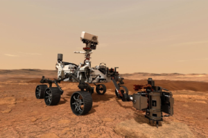
Curiosity is a car-sized rover designed and operated by NASA as part of the Mars Science Laboratory (MSL) mission. Launched in 2011, it landed on Mars in August 2012 in the Gale Crater. The primary goal of Curiosity is to explore the Martian surface and assess whether Mars ever had environmental conditions favorable for microbial life.
Our robot inspiration was from the curiosity robot currently on a space exploration on mars. Curiosity is equipped with advanced scientific instruments to analyze the geology, atmosphere, and climate of Mars. It has a robotic arm, cameras, drills, spectrometers, and environmental sensors. One of its most notable discoveries is finding evidence of ancient water flows and organic molecules, suggesting that Mars may have once supported life. The rover’s success has made it a key mission in the ongoing exploration of Mars.
One major outstanding feature about this robot is the rocker-bogie suspension system, which is designed to maintain stability and allow the rover to traverse the uneven terrain of Mars.
Each of the six wheels on Curiosity is attached to this suspension system, with the front and rear wheels having individual steering motors, allowing the rover to turn in place. The rocker-bogie mechanism ensures that the wheels maintain ground contact while distributing the load evenly, reducing the risk of the rover tipping over when navigating rocky or sloped surfaces.
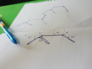
Image below shows the robot in mars and a rough sketch of our first attempt
SLAM TURTLEBOT NAV SETUP
Prerequisites
1. Install ROS: Make sure ROS (e.g., ROS Noetic or ROS Melodic) is installed on your system.
2. Install TurtleBot3 Packages: Install the necessary TurtleBot3 packages.“`bash
sudo apt-get install ros-noetic-turtlebot3-* # For ROS Noetic
“`
3. Set the Environment Variables: Set up TurtleBot3 model variables.
“`bash
echo “export TURTLEBOT3_MODEL=burger” >> ~/.bashrc
source ~/.bashrc
“`
Steps for SLAM Setup
1. Launch TurtleBot3 Simulation (or Real Robot)**:
– For simulation, use `Gazebo`:
“`bash
roslaunch turtlebot3_gazebo turtlebot3_world.launch
“`
– For a real TurtleBot3 robot, ensure it is powered and connected, then run the corresponding launch file.
2. Launch SLAM Node:
– Run the SLAM node (e.g., using Gmapping, which is a popular SLAM method in ROS):
“`bash
roslaunch turtlebot3_slam turtlebot3_slam.launch
“`
3. Teleoperate the TurtleBot:
– Use the keyboard or joystick to manually control the TurtleBot for exploration:
“`bash
roslaunch turtlebot3_teleop turtlebot3_teleop_key.launch
“`
4. View the SLAM Map:
– Open RViz to visualize the map as it’s being created:
“`bash
roslaunch turtlebot3_slam turtlebot3_slam_rviz.launch
“`
Finalizing and Testing
As the robot moves around, it will generate a map of the environment using the SLAM algorithm. Once satisfied with the results, you can save the generated map for future use:
“`bash
rosrun map_server map_saver -f ~/map
“`
This completes the basic setup for testing SLAM with a TurtleBot in ROS.
ROBOT FRAME BUILD
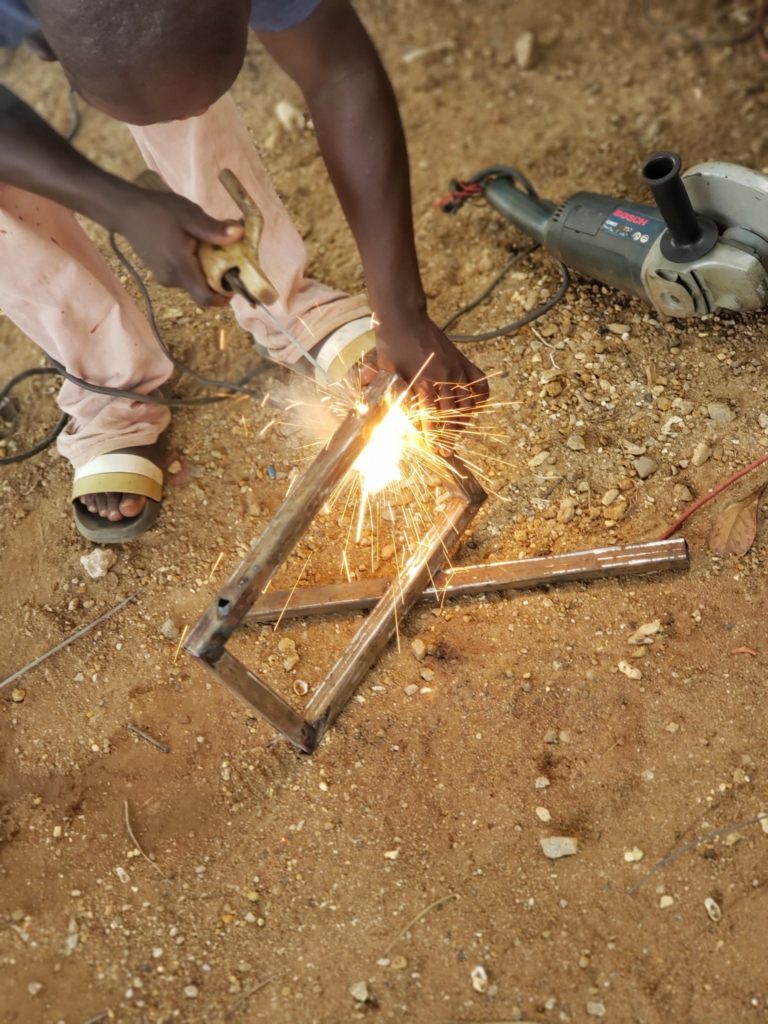
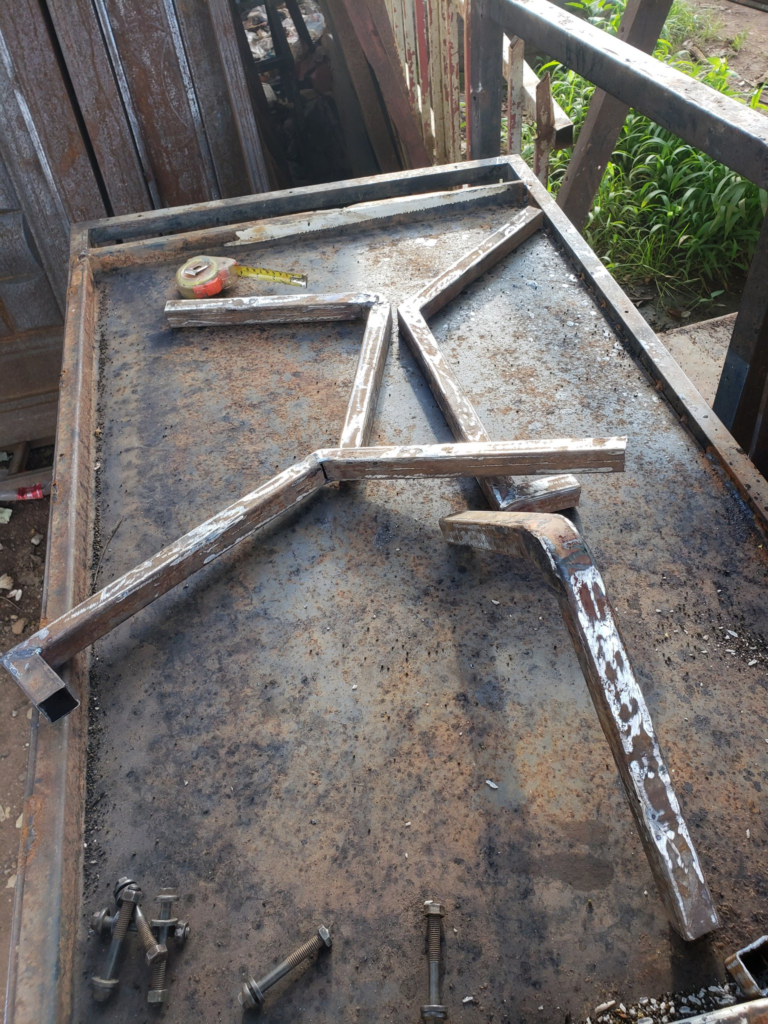
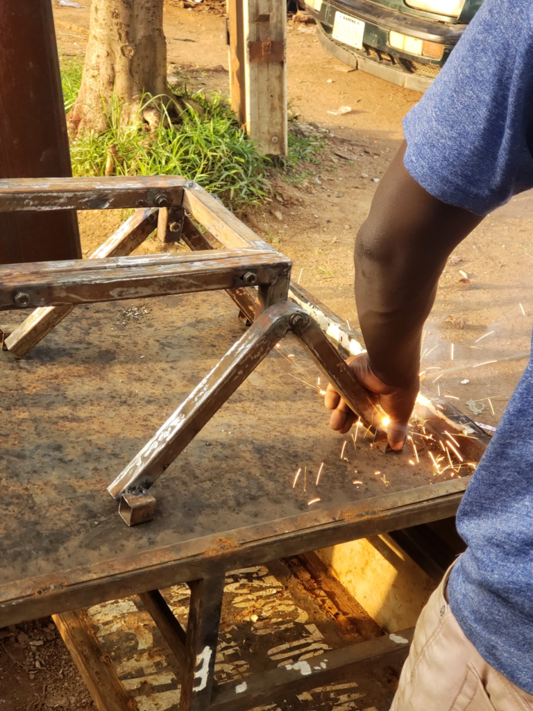
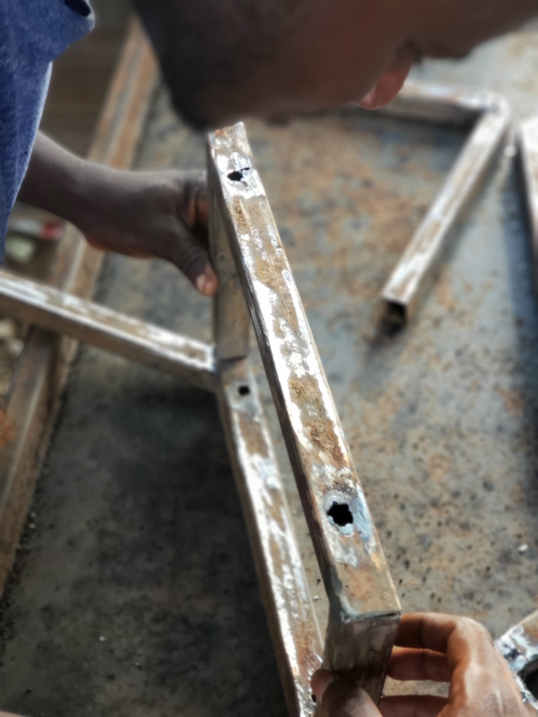
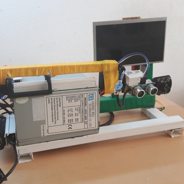
Frame and axel construction, this was made possible using a 1/3 inch black pipe with a relatedly light weight.
Our design was carefully crafted with weight as a key consideration. We recognize that robots can become surprisingly heavy over time, often more quickly than anticipated, so we aimed to keep our overall weight within a manageable range. To achieve this, we deliberately chose lightweight materials for the robot’s housing. This decision was essential in ensuring we stay below a specific weight limit while maintaining strong performance.
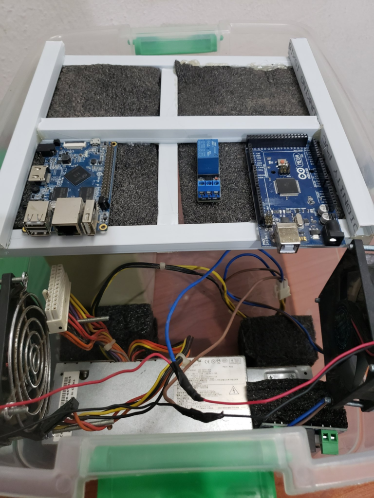
Additionally, we included an electrical housing pipe in our design. This pipe is a vital structural element that organizes and protects all electronic components. We also created specialized bedding to securely hold these electronic parts in place. Our main goal was to position all circuits above, making them easily accessible for maintenance or repairs when necessary.
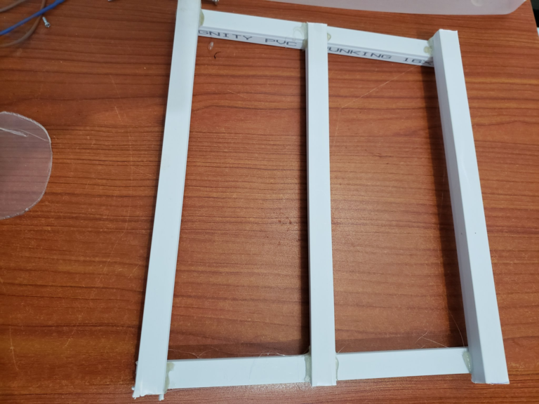
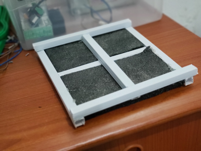
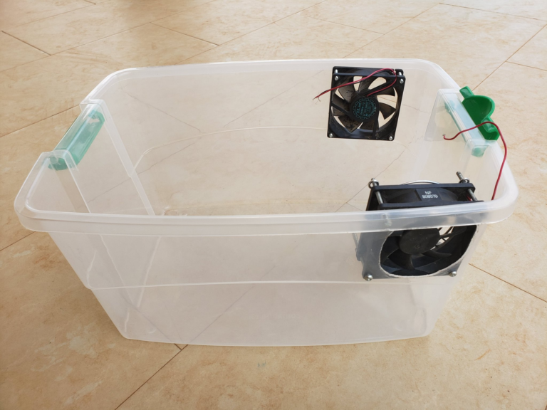
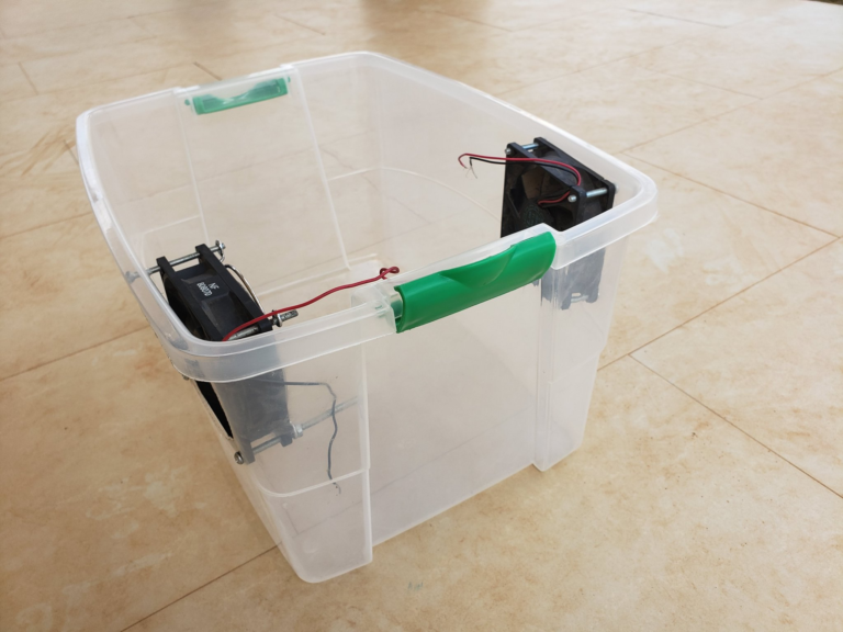
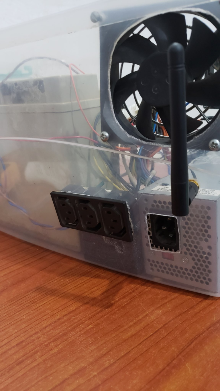
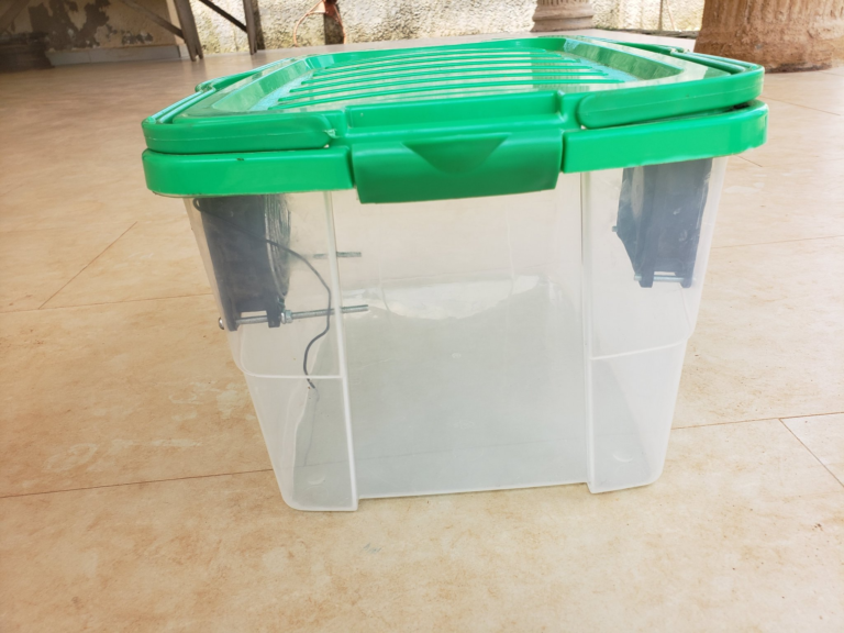
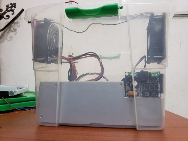
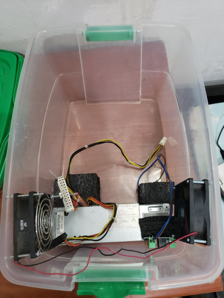
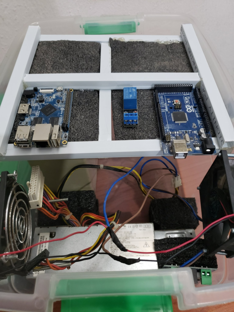
Moreover, we carefully designed the layout so that all heavy accessories, like the battery and charger, are placed at the bottom. This arrangement not only helps balance the robot’s overall weight but also enhances its stability during operation. By locating these heavier components lower down, we reduce the risk of the robot tipping over while in use. Overall, our design approach strikes a thoughtful balance between weight management and functional accessibility, allowing for effective performance and easy maintenance.
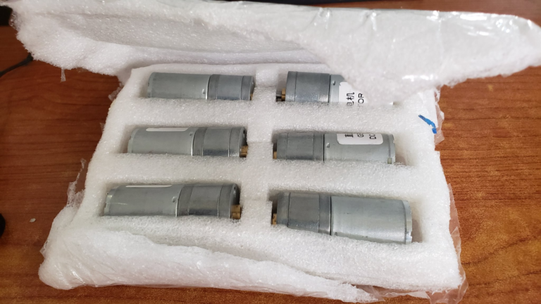
We made a careful decision to select the 12V 45KG Torque Turbo Worm Gear DC Motor that comes equipped with a sturdy metal gearbox and has a speed of 54 RPM. This motor proved to be powerful enough to effectively drive our robot around without getting excessively hot during operation. It performed reliably, allowing us to focus on other aspects of the project without worrying about overheating issues.
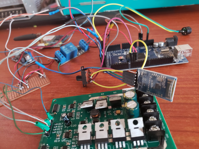
Additionally, we have plans to integrate Bluetooth functionality into our system to enable easy data transfer and facilitate effective communication. To achieve this, we opted for the BT-06 RF Wireless Bluetooth Transceiver Slave Module, which works as an RS232 to TTL UART converter. This module is specifically designed to be compatible with Arduino, allowing us to enhance our project with wireless communication capabilities.
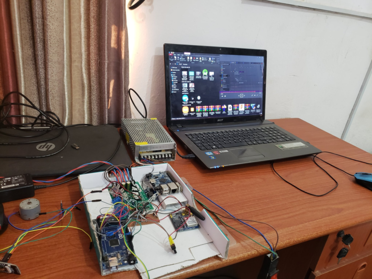
Furthermore, we are incorporating several other essential components into our project. One of these components is the Arduino Mega, which will serve as the main control board, offering the necessary processing power and flexibility for our robot. We are also including a DC-DC converter to ensure stable power supply across different parts of the system. Additionally, a buzzer will be used to provide audio cues or alerts during operation.
We are utilizing relays to manage power distribution and control various electrical components efficiently. Lastly, the project will feature the SIM900A V4.0 Kit, which includes a wireless GSM and GPRS board and an antenna. This addition will enhance our robot’s connectivity and allow it to communicate through mobile networks, making it versatile for various applications. Overall, our carefully selected components will work together to create a functional and innovative robot.
Testrun.
Belo demonstrate bluetooth functionality and response.
This part of our project focuses on breaking down the various components and steps involved in our work. Currently, we are directing our efforts toward the next phase, which involves showcasing SLAM navigation and how we map our environment. This essential process helps us understand and interact with the world more effectively. Additionally, we will explore the important topic of power supply and distribution, examining how we provide power to our systems and ensure that everything operates smoothly and efficiently. Understanding these elements is crucial for the overall success of our project.


