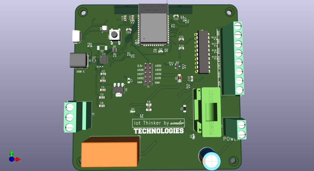
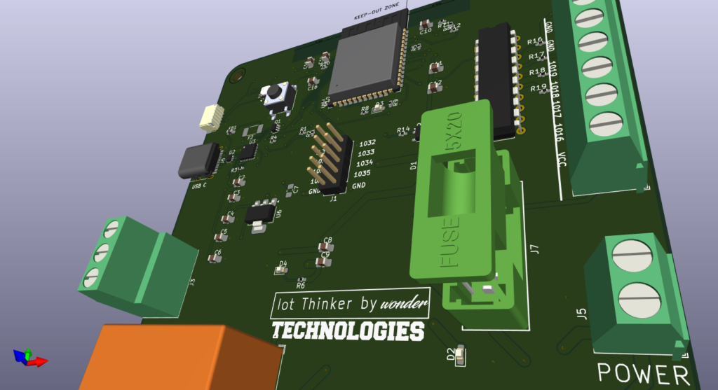
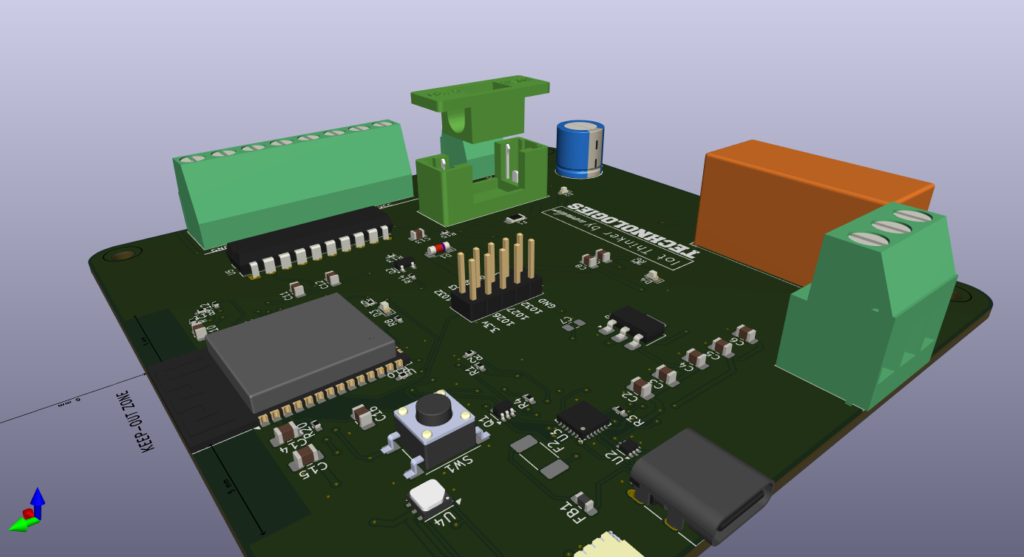
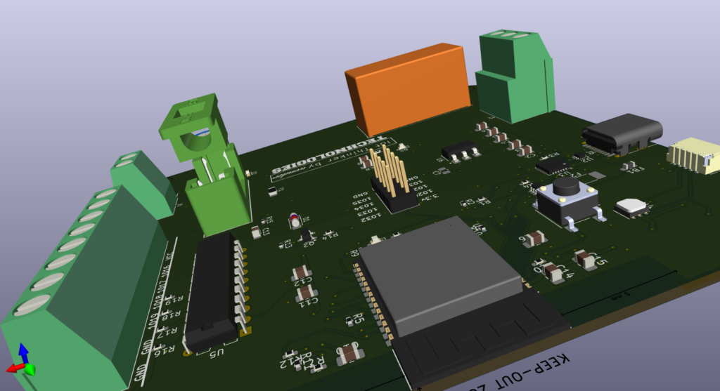
ESP32 IoT Development Board
Introduction
The Internet of Things (IoT) is revolutionizing industries, and creating your own IoT development board is an effective way to learn, innovate, and develop tailored solutions. In this guide, we will outline how to transform a list of electronic components into a fully functional IoT development board, step by step.
Step 1: Understand the Components
First and foremost, grasping the components in your list is imperative. These components are fundamental to the successful design of your IoT board.
Key Components:
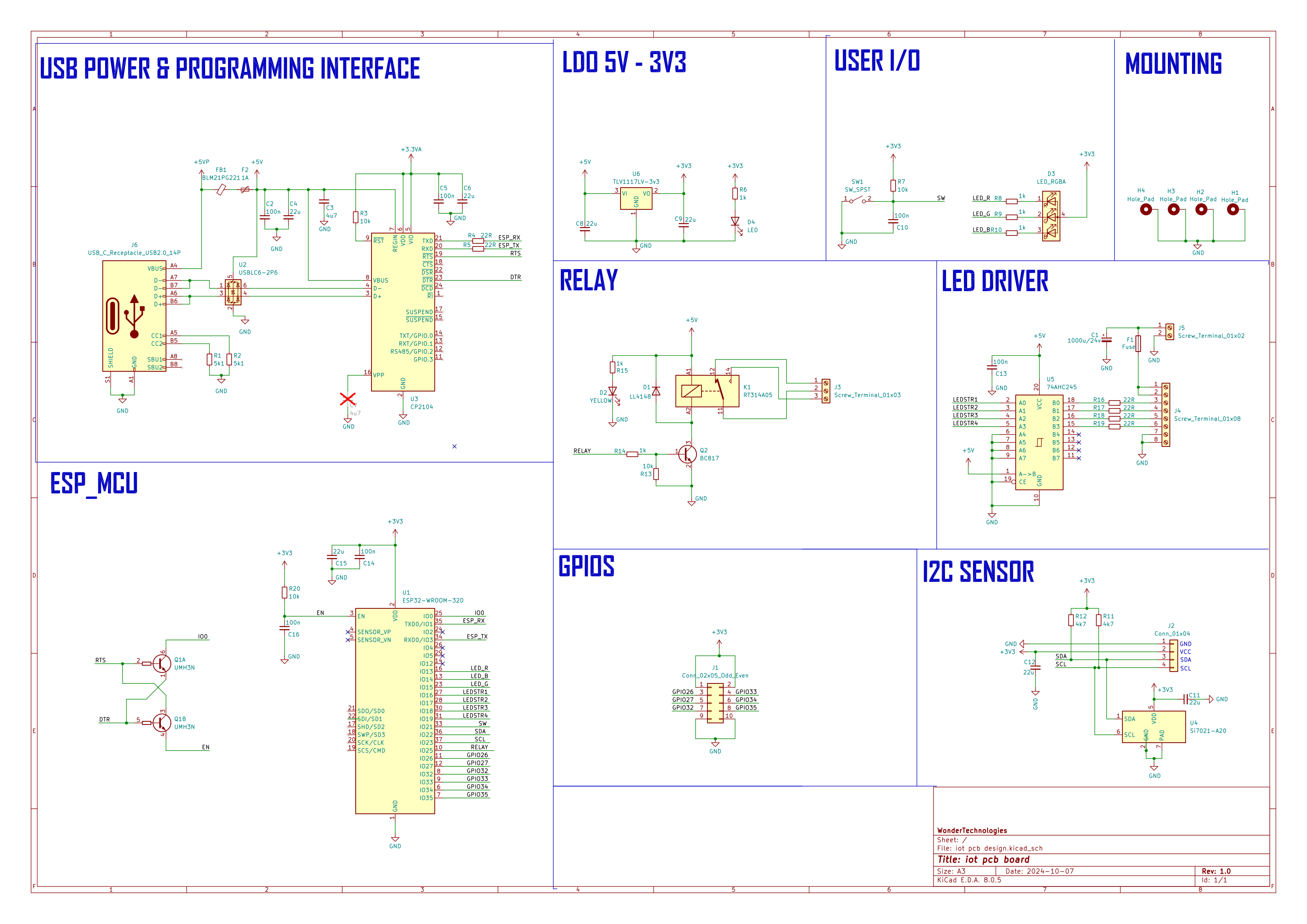
Microcontroller: ESP32-WROOM-32D (U1) – This is the core of your IoT board, equipped with Wi-Fi and Bluetooth capabilities, perfectly suited for IoT projects.
Power Components: Capacitors such as 1000uF/25V (C15), a voltage regulator TLV1117LV-33 (U5), and resistors are vital for maintaining stable power delivery to the board.
Sensors: Si7021-A20 (U3) facilitates humidity and temperature monitoring.
Communication: USB to UART bridge (CP2104, U4) enables reliable communication between your computer and the ESP32.
User Interface: Buttons (SW1) and LEDs (D1, D3, D4) offer an intuitive interface.
Power Protection: Fuses (F1, F3) protect the board from potential power surges.
Connectors: USB-C (J2), pin headers (J6), and terminal blocks (J3, J4, J5) allow for seamless connections to external peripherals.
Step 2: Circuit Design and Schematic Layout
Once you comprehend the components, the next critical step is to create a circuit design that serves as a blueprint for assembling the board.
Tools You’ll Need:
CAD software: Programs like KiCad or Eagle are excellent choices for drafting schematics.
Steps:
Microcontroller Connection: Begin with the ESP32-WROOM-32D (U1) in your design, linking it to the 3.3V output from the voltage regulator TLV1117LV-33 (U5).
Incorporate bypass capacitors such as 100nF (C1, C3) and 1000uF/25V (C15) near the ESP32’s power pins to guarantee stable power.
Power Input: Connect the USB-C (J2) as your primary power source. The USBLC6-2P6 (U2) serves as an ESD protection.
Integrate fuses (F1, F3) in series with the power input for additional safety, including a Polyfuse 1A (F1) to prevent overcurrent.
USB to UART Communication: Add the CP2104 (U4) for conversion of USB signals to UART, facilitating communication with the ESP32 for programming and debugging through USB.
Sensor Connections: Add the Si7021-A20 sensor (U3) to your design, connecting its I2C pins (SDA and SCL) to the ESP32’s I2C interface for humidity and temperature measurement.
LED Indicators: Connect LEDs (D3, D4) to GPIO pins on the ESP32 to function as status indicators. For RGB indication, connect the RGB LED (D1) to three PWM-enabled pins on the ESP32 to manage colors.
Buttons and Switches: Include a push-button switch (SW1) as a reset or input button, linked to a GPIO pin on the ESP32.
Expansion Headers: Connect pin headers (J6) to expose extra GPIO pins for further development. Utilize screw terminals (J3, J4, J5) for effortless connections to external sensors, motors, or other peripherals.
Step 3: PCB Design
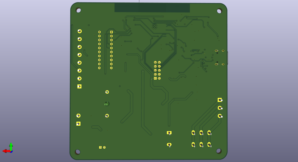
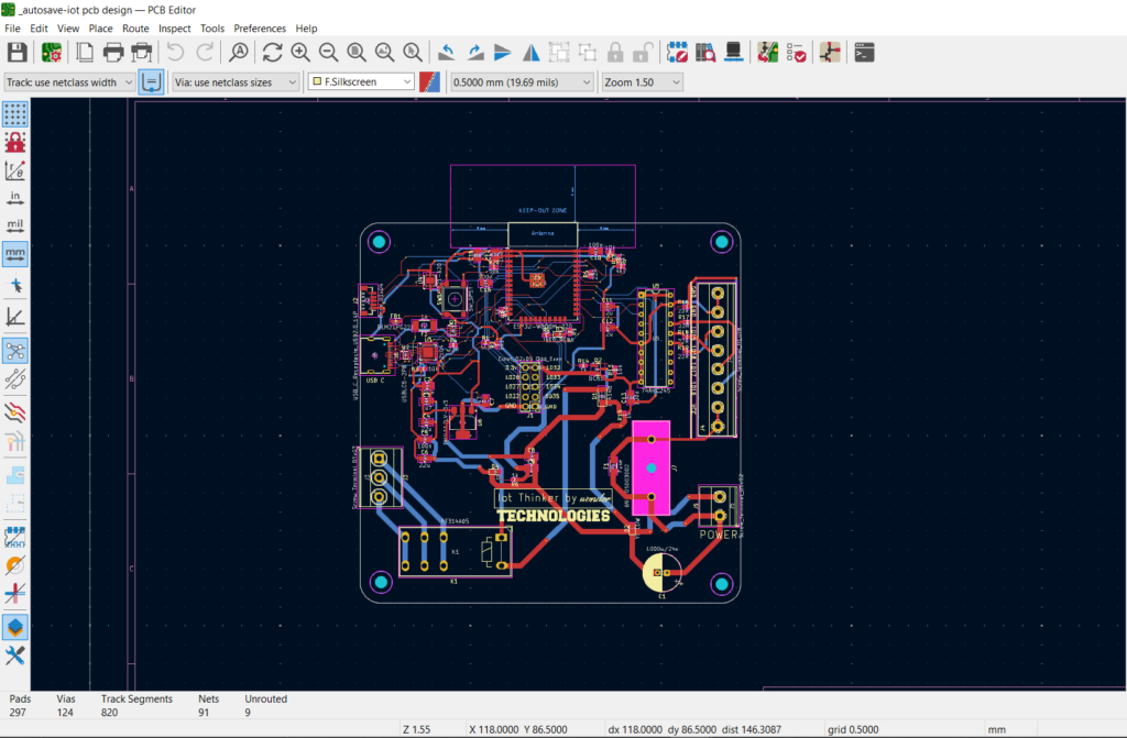
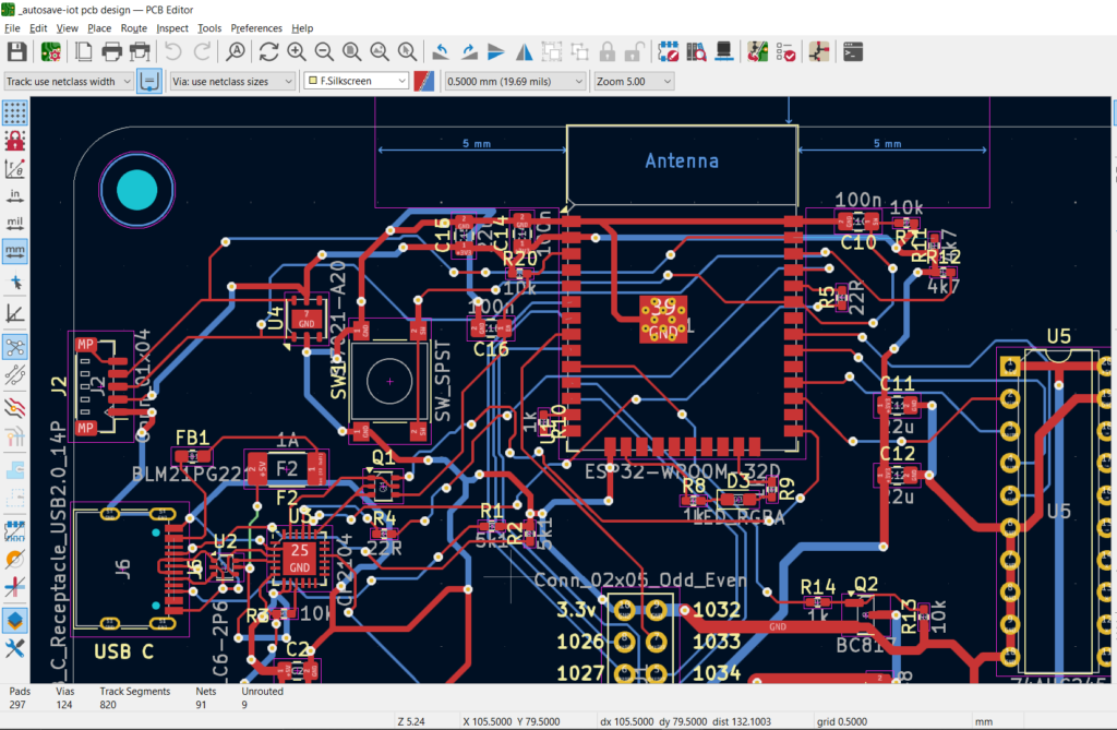
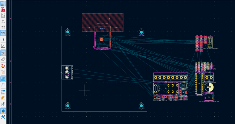
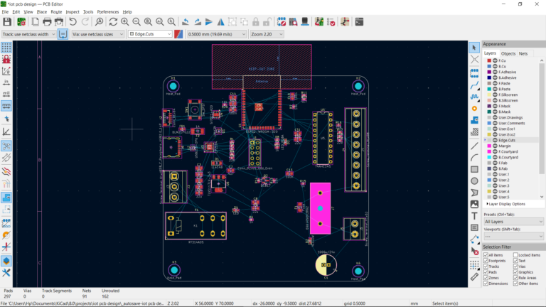
With your schematic finalized, it’s time to design the PCB, which is the physical layout of your board where components are positioned and traces routed.
Steps:
Component Placement:
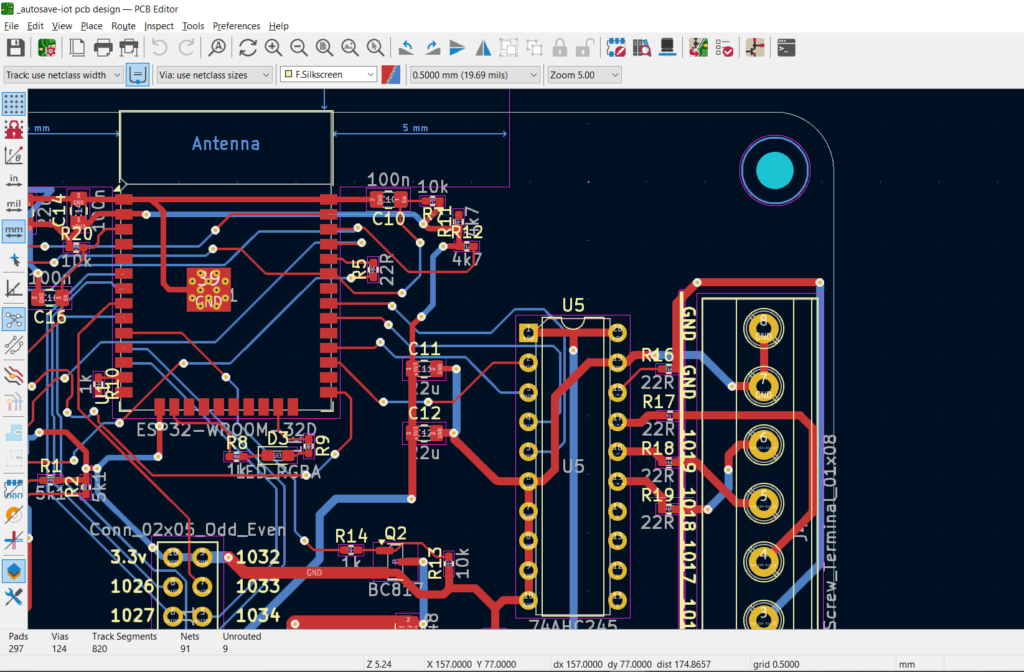
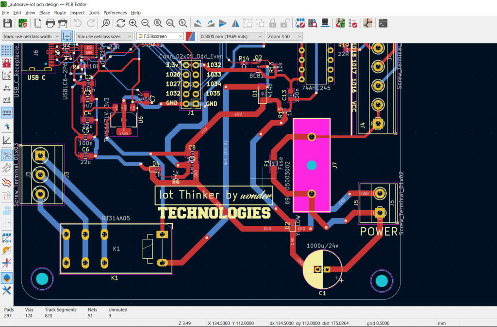
Begin by positioning the main components such as the ESP32 (U1), USB connector (J2), and voltage regulator (U5) centrally.
Position capacitors (C1-C16), resistors (R1-R20), and inductors (FB1) closely to their associated components.
Routing Traces:
Utilize short, direct traces for power and ground lines to minimize noise and maximize efficiency.
Ensure high-speed communication lines, like I2C for sensors, are routed meticulously to avoid interference.
Ground Plane:
Incorporate a ground plane to ensure solid grounding for all components, which effectively reduces electromagnetic interference (EMI).
Final Checks:
Conduct a design rule check (DRC) to verify there are no errors in your PCB design before proceeding to fabrication.
Step 4: PCB Fabrication
After finalizing your PCB design, it’s time to send it to a manufacturer for production.
Steps:
Export Gerber Files: Generate Gerber files from your PCB design software, which the manufacturer will use to fabricate your board.
Choose a PCB Manufacturer: Opt for a service like JLCPCB or PCBWay to manufacture your PCB. Upload your Gerber files, set the board specifications such as thickness and number of layers, and proceed with your order.
Step 5: Soldering the Components
With your PCBs in hand, the next step is to assemble the board by soldering the components.
Tools You’ll Need:
Soldering iron or reflow oven (for SMD components).
Solder wire, flux, and tweezers.
Steps:
Prepare the Board:
Start by applying flux to the PCB pads to ensure clean solder joints.
Place and Solder Components:
Begin with the smaller components, such as resistors (R1-R20), capacitors (C1-C16), and LEDs (D1-D4).
Move on to solder larger components, including the ESP32 module (U1), USB connector (J2), and voltage regulator (U5).
Use tweezers for precise component positioning before soldering.
Test Power Delivery:
After soldering the power components, connect your board to a power source via the USB-C connector (J2). Employ a multimeter to verify the voltage levels are correct (e.g., 3.3V from the TLV1117LV-33 regulator).
Solder Remaining Components:
Solder the remaining connectors, sensors, buttons, and ICs. Ensure all connections are robust and free from shorts.
Step 6: Programming the ESP32
With the hardware assembled, it’s time to program the ESP32 microcontroller.
Steps:
Install Arduino IDE or PlatformIO:
Utilize the Arduino IDE or PlatformIO for development, ensuring to install the ESP32 board package in the IDE for compatibility with your module.
Basic Blink Test:
Write a simple blink test to confirm the ESP32 and connected LEDs are operational.
Add Sensor Functionality:
Implement libraries like Wire.h for I2C communication with the Si7021 sensor, programming your ESP32 to retrieve data and transmit it via Wi-Fi or Bluetooth.
Connect to a Cloud Service:
Develop code to transmit sensor data to an IoT cloud platform such as AWS IoT, Blynk, or ThingSpeak for real-time monitoring.
Step 7: Testing and Debugging
Once the firmware is uploaded, it’s crucial to test your board:
Power Supply: Confirm that the board powers up correctly.
Sensors and LEDs: Test the sensors, LEDs, and switches to validate functionality.
Wi-Fi Connectivity: Ensure that your ESP32 establishes a Wi-Fi connection and communicates effectively with your selected cloud platform.
